This community is for electronic hobbyists to discuss projects and is focused on soldering. Everyone is welcome from the noob to people who have been soldering as a hobby for decades to people who solder professionally. We'll talk about materials and techniques, equipment, and projects. Everyone is welcome. All questions are welcome. Post photos and ask for help.
If you’ve seen a question 100 times answer it the 101st time or ignore it. Even better, write a complete, detailed answer and suggest that the mod(s) pin it to the community.
Don't tell other users what they should have done of that what you do is better. You do what you want to do and let other people do what they want to do. What is best for you might not be best for others.
[Did you actually think there were 98 rules?]
If you present something as fact and are asked to provide proof or a source provide proof or a source
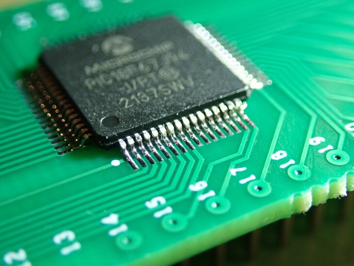
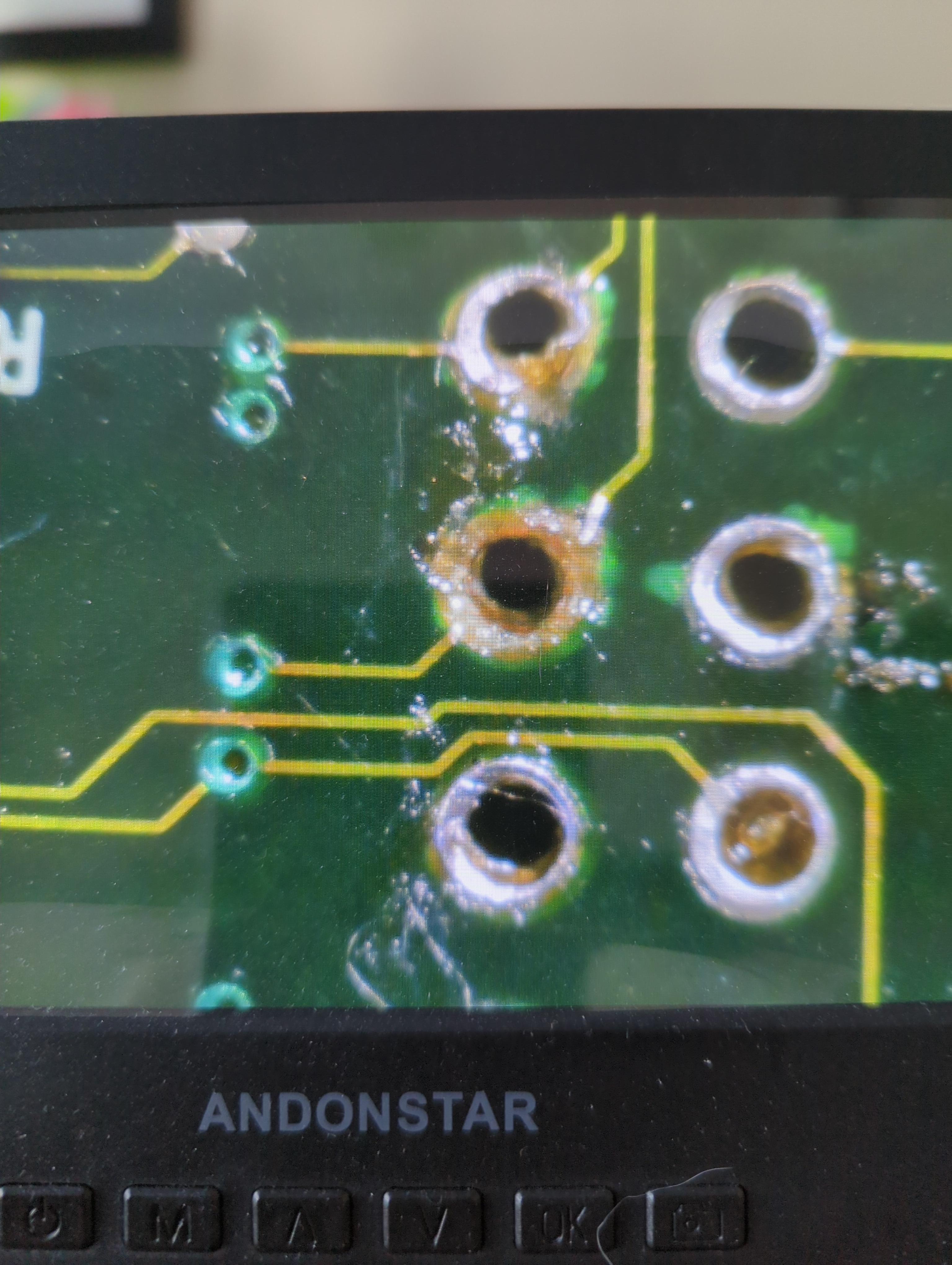
I used a pointed tip, flux, and added some of my own solder to the via. I then cleaned, added new flux, and used solder wick to remove the solder. Some points, would NOT melt at all. I kept increasing the temp to 430°c and it finally melted and took everything with it.
Now, I know I fucked up and used too much heat. I probably should have used my rework station and a solder sucker but I JUST got the rework station and didn't want to popcorn the OG Xbox board... The solder wouldn't stay melted long enough from my i
I soldered the Schmitt trigger onto a BoB then bodged it onto the HMI board using 0.3mm bodge wire. The controller is an ESP32 and I was having trouble with the hardware interrupts because the RC debounce I was using was too slow. The Schmitt trigger gives me a nice, square signal which the controller interprets properly. The chip cost me a couple of bucks from Digikey.
Here's the best RC trace I could get.
and here's the trace with the Schmitt trigger (same scope settings.)
I usually use an optical microscope at work. Makes hand eye coordination better so even if my hands are shaky, I can solder 0402 easily. Digital scopes are pretty hard to use on account of the lag
SMT ICs I check back with the microscope after reflow / rework
Considering getting one for home use but I dont have the space. Need to make like 20k more a year to be able to afford renting somewhere and got knows how things will go the next couple of years
Discover the magic of the internet at Imgur, a community powered entertainment destination. Lift your spirits with funny jokes, trending memes, entertaining gifs, inspiring stories, viral videos, and so much more from users.
I made this 'fix' about 7 years ago and the device is still in use today. I know which one it is because my 5ohm resistor came out around 4.9 so the device always runs 2% out of spec.
This was the first time I've used a stencil and solder paste to build up a pcb. It was so much easier to get all the components aligned and soldered on the board (on the back, there are 38 0603 capacitors which are always time consuming to hand solder). After just had to clear a few bridges and added a little extra solder to U1.
I recently got this cheap USB dac thats plugged into my pc over USB - B but it still needs Micro USB power for some reason. So I thought I could just connect the 5V from the USB A port to the Micro usb's. Is there any reason why this doesn't work?
I'm working on replacing the Schneider SmartRelay on an Atlas Vista 613 wheelchair lift that I bought for my dad. The Atlas technician agrees that the SmartRelay is probably shot and the replacement is $1,000 wholesale. I built a replacement using an Arduino Nano, a UNL2803A Darlington array, a switching 7805, a bunch of Zener diodes, and a handfull of Schneider industrial relays.
Unfortunately, I let the smoke out of my very last Nano and needed to keep the project moving. So...I took a small piece of protoboard, an Arduino ProMini 168, and some jumper wire and created this Frankenduino. It's the same pinout as the Nano with none of the nice supporting stuff like an ICP port, USB, voltage regulators, etc. It will keep the development moving while I'm waiting for the 10 Nanos I have on order to arrive.
With maple syrup season fast approaching (4 months ish) my thoughts have turned to working on the Sapmaster once again. I'm going to design and build a new top and bottom board this year to fit in the BUD DMB-4774 DIN case that I use for the SapMaster controller. That's going to involve a bunch of SMD soldering which reminded me of the irritation that soldering with loose pieces of SMD tape causes me.
To that end, I went looking for an SMD dispenser cartridge that would meet my needs. I couldn't find one so I decided to design my own.
This is version 4.1 of the design. It holds around 5 feet of standard 8mm paper tape which is around 1,000 components. The tape comes out the straight slot at the upper right. The clear cover tape goes out the curved slot and can be hooked under the little pin upper left. The point of the splitter between the straight and curved slots holds the components in place so they don't fall out before you pull the tape out of the slot.
I've posted a few videos now of myself soldering header strips and some SMDs with my good quality soldering tools and with an inexpensive soldering iron that I bought at Walmart. I sent a link to the friends, the hardware designed and programmer, who I often work with. One designs the boards, the other programs them. I do some of their fine soldering work for them.
They were amused by the Walmart soldering iron videos and remarked that they were surprised that soldering QFPs was even possible with that iron.
That got us to talking and me to thinking. What is the difference between the tools and materials and the technique used by someone who makes it look easy and the tools and materials and the technique used by beginners who struggle?
I would like to propose that the biggest issue that beginners have is flux management.
Electronic solder isn't a solid metal wire. The solder we use for electronics most often includes flux. The flux is included in one or more cores inside the
In this video I used the $15.88 Walmart soldering iron and the unknown Chinese solder that came with it to solder a DS1307 real time clock in a SOIC-8 package.
In this video I used the $15.88 Walmart soldering iron and the unknown Chinese solder that came with it to solder 2.54 mm header strips onto a small adapter board.
In this video I go back to the beginning of my more than 45 years of experience soldering and buy a $15.88 Chinese soldering iron from my local Walmart store and compare it to a Weller PES51 pencil iron connected to my WESD51 soldering station and a Hakko FM-2027 connected to my FM-203.
I have said that you can use the cheapest soldering iron to solder SMD devices like SOIC-8s and QFP-32s. In subsequent videos I will attempt to solder pin headers, a DS1307 real time clock in a SOIC-8 package and a LGT8F328P MCU in a QFP-32 package.
The goal of these videos is to make clear that even beginners can solder modern SMD devices using basic soldering equipment that is readily available locally to most people.
Hakko FM-2023 station with MF2027 handle and T15-D16 tip
When I started soldering everything was big and had leads that went through holes in the board. You inserted the leads, bent them over to hold the component, flipped the board over, soldered everything, and trimmed off the excess leads.
Now I'm soldering things down to 0402 SMDs (1/4 the size of the smallest component in the picture) using a needle point soldering tip and a microscope.
A pair of 2N2222 transistors, one SOT23 and one TO-92.
I got myself a T12 clone station recently. I've only had a junk iron that plugs into a wall socket and heats up to full blast whatever temperature with the big giant tip. Not very useful for more precise work.
I had this damaged Arduino Pro Micro clone sitting in my box of random stuff. At some point in time I had decided cut out out 4 pin headers for some reason. Damaged the corresponding traces in the process.
The repair worked! It was the MOSI, MISO, CLK, and RESET pins on the board. These pins can be used to have this board flash another Arduino board.
I am a beginner at soldering and am trying to assemble a number of these small pcbs. In the process, I have to solder SK6812 MINI-E LEDs and am struggeling to get that right. My problem is that the LEDs tabs are almost exactly as large as the solder pads on the PCBs and if I apply solder and flux to the pads and try to use hot air to settle the tabs into place, they tend not to stick to the pads and if I try to put them in "dry" and solder them with the soldering iron (like a through hole connection), I have trouble getting solder between the tab and the pads. Any advice? Any video that shows how to solder this kind of joint?


